

Product Consultation
Your email address will not be published. Required fields are marked *
A heating coil is fundamentally a specialized thermal conductor designed to convert electrical energy or stored thermal energy into radiant and convective heat. The core conclusion is that the efficiency, lifespan, and safety of any thermal management system depend almost entirely on the correct selection of the heating coil material, geometry, and power density for its specific operating environment. Understanding these variables allows engineers and technicians to prevent premature failure, optimize energy consumption, and ensure precise temperature control in any given application.
To utilize a heating coil effectively, one must understand the physics governing its operation. While there are multiple ways to generate heat using a coiled structure, the underlying goal is always to transfer energy to a target medium, whether that medium is air, liquid, or a solid surface.
The most common mechanism relies on Joule heating, also known as resistive heating. When an electric current passes through a conductive material with inherent resistance, the electrical energy is converted into thermal energy. The coil shape is deliberately chosen because it allows a long length of resistance wire to be packed into a compact physical space. This high density of wire generates a significant amount of heat per square inch. The geometry of the coil also dictates the surface area available for heat dissipation, directly influencing how quickly the surrounding environment absorbs the thermal energy.
In hydronic and steam systems, the heating coil operates as a heat exchanger rather than a heat generator. A hot fluid, such as heated water or steam, travels through the interior of the coiled tube. As the fluid moves, heat conducts through the metal walls of the coil and is transferred to the cooler external medium, typically air. The coiled shape induces turbulence inside the tube, which scrubs away the boundary layer of slow-moving fluid against the tube wall. This turbulent flow significantly increases the thermal transfer coefficient compared to a straight pipe, making the heating process much faster and more responsive.
The material composition of a heating coil dictates its maximum operating temperature, oxidation resistance, and mechanical stability under thermal stress. Selecting an inappropriate material is the primary cause of catastrophic coil failure.
For electric heating elements, Nichrome—a blend of nickel and chromium—is the industry standard. Its popularity stems from its remarkably stable resistance across a wide temperature range, meaning it does not require complex external controls to prevent power surges as it heats up. Furthermore, when Nichrome is heated, it forms a protective layer of chromium oxide on its surface. This passive layer prevents the underlying metal from further oxidizing, allowing the coil to operate in open air at high temperatures for extended periods without thinning or breaking. In more extreme environments, iron-chromium-aluminum alloys are utilized because they offer even higher maximum operating temperatures and a stronger oxide layer.
When the coil acts as a fluid heat exchanger, copper is frequently chosen due to its exceptional thermal conductivity. A copper coil can transfer heat to the surrounding air much faster than most other metals, reducing the required size of the equipment. However, copper is susceptible to corrosion in certain water conditions. In situations involving corrosive fluids, deionized water, or high sanitary requirements, stainless steel becomes the material of choice. While stainless steel possesses only a fraction of the thermal conductivity of copper, its mechanical strength and corrosion resistance make it indispensable in harsh industrial and food-processing environments.
The physical shape of a heating coil is just as important as the material it is made from. Engineers manipulate the geometry of the coil to solve specific thermal challenges.
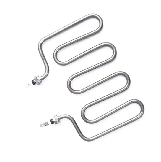
A helical coil resembles a stretched spring, where the loops do not touch. This design is critical for electric resistance wires because it prevents the loops from short-circuiting against one another. The gap between the loops allows air to flow freely through the coil, carrying heat away efficiently. Conversely, a spiral or pancake coil features loops that lie flat against one another in a single plane. This design is typically used when concentrated, directional heat is required, such as in surface heating applications. The spiral design restricts airflow but maximizes the heat density in a specific footprint.
When a fluid-carrying coil is used to heat air, a plain metal tube is often insufficient because air is a poor conductor of heat. To overcome this, fins—thin metal plates or spirals—are mechanically attached to the exterior of the coil. These fins drastically expand the surface area of the coil without significantly increasing its volume. The addition of fins to a heating coil can increase the effective heat transfer surface area by several times, allowing the system to raise air temperatures rapidly while keeping the internal fluid temperature relatively low. This not only improves efficiency but also protects the coil from thermal fatigue.
The versatility of the heating coil allows it to be integrated into a vast array of systems. Its application dictates the specific design parameters required for reliable operation.
In commercial and residential heating, ventilation, and air conditioning systems, the heating coil serves as the primary heat exchanger. Hot water from a boiler or refrigerant from a heat pump is pumped through a multi-row finned coil. As return air from the building is drawn across the coil by a blower fan, the heat is absorbed, and the warmed air is distributed back into the living space. The size of the coil, the number of fins per inch, and the number of rows directly determine the heating capacity and the air pressure drop across the system.
Manufacturing facilities rely heavily on immersion heating coils. These are submerged directly into liquid baths, such as chemical tanks, oil reservoirs, or molten metal vats. Because the liquid completely surrounds the coil, heat transfer is highly efficient. However, the coil must be designed to withstand the specific chemical properties of the fluid. For highly corrosive environments, the coil may be housed in a protective sheath or constructed from exotic materials like titanium to prevent rapid degradation.
On a smaller scale, heating coils are the working heart of everyday appliances. In an electric oven, a tightly wound Nichrome coil glows red to radiate heat onto food. In a clothes dryer, a massive coil heats the air stream that tumbles through the wet laundry. Even in baseboard heaters, long electric coils are encased in metal fins to provide silent, radiant convective heat along the floor of a room. In these applications, the coil design prioritizes safety, ensuring that the high temperatures do not ignite surrounding structural materials.
Even the most robustly designed heating coil will eventually fail if exposed to conditions outside its operational limits. Identifying the root cause of failure is essential for implementing long-term solutions.
The most prevalent cause of electric coil failure is thermal cycling. Every time power is applied, the coil expands as it heats up; when power is removed, it contracts as it cools down. Over thousands of cycles, this constant expansion and contraction cause the metal to crystallize and become brittle. Eventually, microscopic cracks form at the points of highest stress, typically near the terminal connections or the support structures. Once a crack forms, it concentrates the electrical current, causing localized overheating that quickly leads to a complete break in the wire. Mitigating this requires using alloy materials specifically formulated to resist thermal fatigue and designing support structures that allow the coil to flex freely without restraint.
If an electric coil is operated in an oxygen-rich environment at temperatures exceeding its material limits, the protective oxide layer breaks down. The base metal begins to rapidly combine with oxygen, causing the wire to thin and eventually burn open. In applications involving plastics or organic materials, carbonization poses a severe risk. If organic vapors come into contact with a coil that is too hot, the vapors pyrolyze, leaving a hard carbon deposit on the coil surface. Carbon is highly conductive, and these deposits will eventually bridge the gaps between the coil loops, causing a short circuit and immediate failure. Keeping the coil temperature well below the pyrolysis point of surrounding materials is the only effective prevention method.
In liquid heat exchangers, mineral scaling is a constant threat. When hard water is heated inside a coil, minerals like calcium and magnesium precipitate out of the solution and adhere to the inner walls of the tube. This scale acts as a thermal insulator. Because the heat cannot easily transfer through the scale to the water, the metal tube itself overheats. The coil may eventually fail not because of external conditions, but because the internal fluid was insulated from the metal. Regular descaling maintenance and the use of water softeners are critical to maintaining the efficiency and structural integrity of fluid heating coils.
To clearly illustrate how different coil characteristics match specific operational needs, the following table summarizes the primary distinctions between common configurations.
| Coil Type | Primary Material | Best Suited Medium | Key Advantage |
|---|---|---|---|
| Open Electric Coil | Nichrome Alloy | Open Air | Rapid heat-up, high temperature capability |
| Finned Hydronic Coil | Copper with Aluminum Fins | Forced Air | Maximum surface area for air heat exchange |
| Corrosive Immersion Coil | Stainless Steel or Titanium | Aggressive Liquids | Chemical inertness and structural longevity |
| Inline Steam Coil | Carbon Steel or Copper | Pressurized Steam | Extremely high heat transfer rate via latent heat |
Proactive maintenance is the most cost-effective method to extend the functional life of a heating coil. Relying on reactive replacement leads to unnecessary downtime and increased operational costs.
Routine visual inspections should focus on identifying discoloration, deformation, or sagging of the coil structure. A uniform dark oxide color is normal for an electric coil, but localized bright spots, blistering, or warped supports indicate severe hot spots and impending failure. Electrically, technicians should regularly measure the resistance of the coil using a multimeter. A resistance reading that deviates significantly from the factory specifications indicates that the wire has thinned due to oxidation or that a partial short circuit has developed between loops.
For finned heating coils, air-side fouling is a major efficiency drain. Dust, dirt, and grease accumulate on the fins, acting as an insulating blanket that traps heat inside the coil and prevents it from entering the air stream. This forces the system to run longer and at higher temperatures to achieve the desired space heating. Regular cleaning using compressed air, soft brushes, or specialized chemical cleaners restores the thermal conductivity of the fins. In liquid applications, flushing the system with appropriate descaling agents dissolves mineral buildup, ensuring that the internal fluid maintains maximum contact with the metal walls.
Because heating coils operate by generating high temperatures, their integration into a system must be governed by strict safety protocols to prevent fires, electrical shocks, and thermal injuries.
No heating coil should ever be operated without an independent, secondary safety device. A high-limit thermal cutoff switch is a fuse-like device wired in series with the coil. If the primary temperature controller fails and the coil begins to exceed its safe operating temperature, the thermal cutoff breaks the circuit permanently. Unlike a standard fuse that reacts to electrical overcurrent, a thermal cutoff reacts directly to physical temperature, providing an absolute last line of defense against thermal runaway.
In immersion and enclosed coil applications, the live resistance wire must be electrically isolated from the outer metal sheath. This is achieved using compacted magnesium oxide powder, an excellent electrical insulator that also happens to be a superb thermal conductor. If the coil is cracked or bent sharply, the magnesium oxide layer can shift, creating an internal short circuit to the outer sheath. Proper grounding of the coil sheath is mandatory; if an internal short occurs, the ground fault ensures the electricity trips a breaker immediately rather than energizing the surrounding equipment or liquid.
Installing a heating coil requires strict adherence to minimum clearance specifications. Combustible materials located too close to an electric coil can undergo pyrolysis and ignite spontaneously over time, even if they do not touch the coil directly. Furthermore, forced-air systems must never be operated with a blocked intake. If the blower fan fails while the heating coil remains energized, the stagnant air around the coil will rapidly reach ignition temperatures. Interlocking the coil power supply with an airflow sail switch ensures that the coil cannot receive power unless air is actively moving across it.
While the fundamental physics of the heating coil remain unchanged, the methods of manufacturing, controlling, and integrating them are evolving rapidly to meet modern demands for energy efficiency and precision.
One of the most promising developments is the application of nano-ceramic coatings to electric heating coils. These specialized coatings are applied via plasma spraying and create an exceptionally hard, inert surface over the resistance wire. This technology addresses two major failure modes simultaneously: it prevents the underlying alloy from oxidizing, and its non-porous nature prevents carbon buildup from adhering to the wire. As a result, coated coils can operate at higher power densities without degrading, allowing engineers to design smaller, more compact heating systems without sacrificing longevity.
In the realm of fluid coils, traditional round tube and fin designs are facing competition from microchannel technology. Instead of a few large tubes, microchannel coils utilize flat aluminum tubes containing dozens of tiny internal channels. This geometry massively increases the internal surface area in contact with the fluid while reducing the overall volume and weight of the coil. While initially developed for refrigeration, microchannel heating coils are increasingly being adopted in HVAC systems where space constraints and material costs are primary concerns.
The integration of smart sensors directly onto or into the heating coil is transforming maintenance from a scheduled chore into a predictive science. By embedding micro-temperature sensors and current monitors, a smart coil can track its own degradation in real time. Algorithms analyze the rate of resistance change or the pattern of thermal response times to predict exactly when the coil will fail. This predictive capability allows facility managers to replace a heating coil during a planned downtime window rather than reacting to an unexpected catastrophic failure that halts production.
When evaluating or specifying a heating coil for any system, the primary variables must be balanced against one another to achieve optimal performance.
How to choose the right infrared heater element for industrial drying?
Apr 15,2026
What Is the Difference Between Various Cartridge Heater Element Types?
May 01,2026Your email address will not be published. Required fields are marked *


